From the previous publication related to carbon capture, it can be concluded that it will be a fundamental technology in meeting climate goals, being a key piece in the puzzle of producing high-value-added renewable compounds such as methanol or SAF (synthetic kerosene). Thus, for a successful development of the technology, it is necessary to understand its implications both in economic (CAPEX and OPEX) and technical terms. In this way, one might ask:
- How do impurities affect the process?
- What costs does a capture plant imply? What CO₂ costs are involved?
- In addition to the initial investment, what other expenses do these types of facilities entail (energy, maintenance, auxiliary raw materials…)?
- How is a capture facility integrated with a renewable fuel plant?
- What implications can a capture plant have in an existing process?
In this article from AtlantHy Academy, we will address all these aspects and answer the questions based on the knowledge we have acquired during the development of these types of projects.
Impurities from the emission source
Depending on the CO2 emission source, the exhaust gas may contain more or fewer impurities, mainly particles, sulfur compounds, and nitrogen compounds. The presence of these contaminants can cause problems in the nominal operation of the plants, from damage to mechanical equipment (impact of particles) to the formation of degradation products of chemical solvents due to chemical reactions between amines and nitrogen and sulfur compounds. In the case of degradation products, these are vitally important since they can be corrosive to steel and eventually cause loss of containment in the process units.
To avoid these phenomena that affect plant operation and may lead to unexpected shutdowns or lower efficiency, adequate pretreatment of the exhaust gas must be designed before it enters the capture plant. In the case of amines, this pretreatment mainly consists of stages for removing particles and stages for removing sulfur and nitrogen oxides using auxiliary raw materials such as sodium hydroxide. In the case of other technologies such as cryogenics, the previous stage for removing sulfur and nitrogen compounds may be dispensable, as the process is not as sensitive to these impurities, and they can be easily removed through differences in the boiling points of the contaminants and CO2.
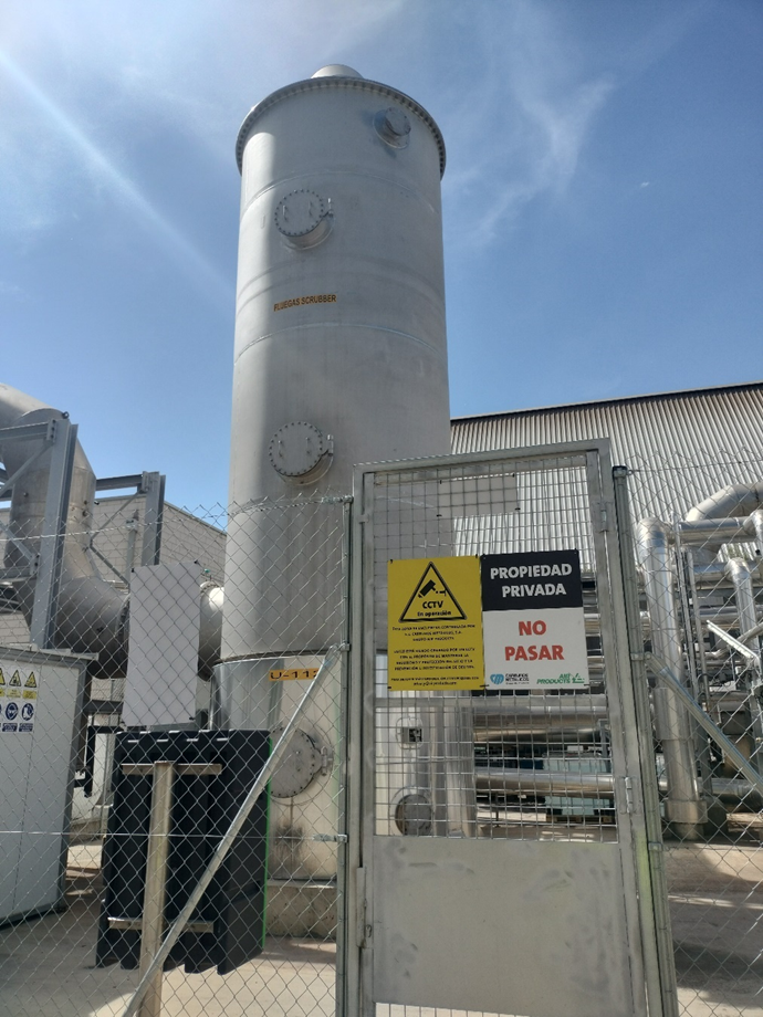
Illustration 1. Scrubber for removing contaminant compounds present in the exhaust gas.
Regarding the presence of particles, a bag filter-based system can be used to ensure that no solids are introduced into the capture plant pipelines, ensuring the integrity of the mechanical equipment and reducing the probability of operational problems.
Investment and CO2 production costs
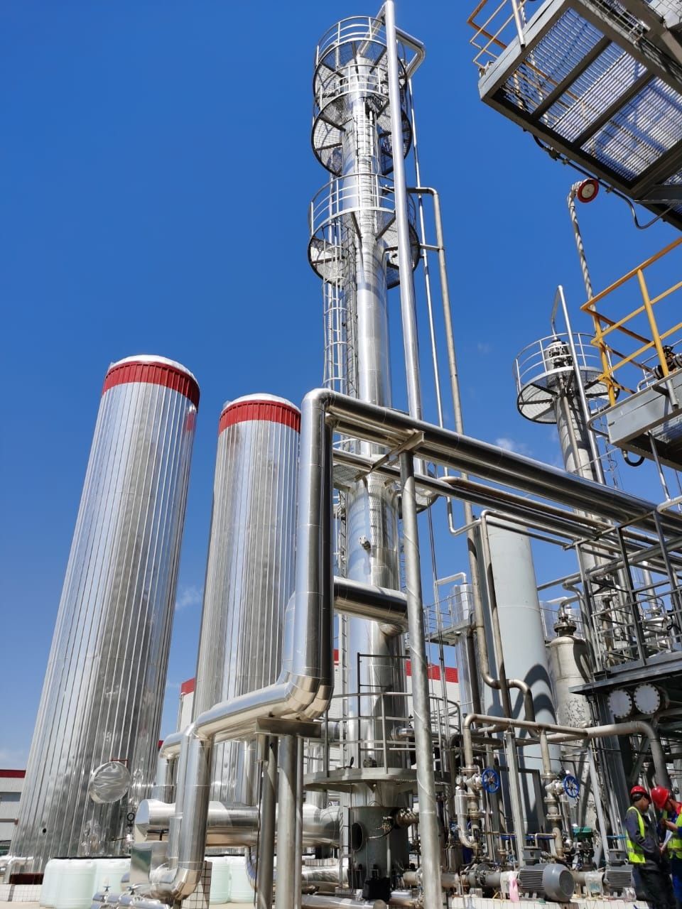
Capture plants are very similar to conventional chemical plants, as they are composed of units widely known in the industry such as separation and absorption columns, fluid and gas flow equipment, storage tanks, and heat exchange and cooling equipment. Since the equipment used is not new, its costs are very similar to those used in the industry for decades.
As for the parameters that most affect the costs of this type of plant, the concentration of carbon dioxide stands out mainly, as the higher the concentration, the cheaper the capture process will be due to the need for smaller and therefore less expensive equipment, and the type of technology used (amines, carbonates, cryogenics…).
Another key factor is the well-known economy of scale effect, as the equipment used does not increase its cost proportionally to the scale but follows an exponential function that allows larger projects to achieve more competitive investment costs than smaller ones and, therefore, produce CO2 at a lower cost (the famous six tenth rule).
Regarding operational expenses, they are mainly marked by the high need for thermal energy, so this type of energy defines the operational expenses of this type of plants throughout their entire lifespan.
As guidance, a capture plant with a capacity of 100,000 t CO2/year based on amines and used in an exhaust gas stream with a 9%vol CO2 concentration could require an investment of between €40 – 50 million.
Based on the estimated investment costs for this type of plant, indicative values can be obtained for the cost of CO₂ produced depending on the concentration of the emission source and the flow magnitude. Thus, an estimate of the expected carbon dioxide costs depending on the specific case is provided in the following illustration.
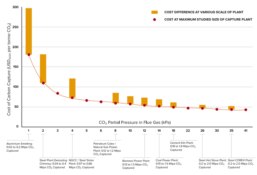
Illustration 2. CO₂ capture costs based on the source and magnitude of the exhaust gas flow. Source: (Global CCUS Institute, 2021).
Energy and auxiliary raw material consumption in capture plants
To achieve the separation of carbon dioxide from the exhaust gas stream, depending on the technology, an input of electrical and/or thermal energy is required, which must be of renewable origin or have a low carbon intensity. This need for energy inputs to be renewable is because the carbon dioxide, although captured and not directly emitted, will have a carbon footprint associated with both its origin and the capture process in which it is obtained in pure form. Therefore, that carbon intensity will be transferred to the final product obtained (SAF, methanol…) and may mean that the resulting RFNBO does not comply with the stipulations in RED III regarding the reduction of greenhouse gas (GHG) emissions.
Electricity consumption
Electricity consumption is mainly due to fluid flow equipment such as amine recirculation pumps in absorption technology, blowers to counteract the pressure drop in the CO2 absorption and desorption columns, or for compressors and cooling equipment in the case of cryogenic technology. Regarding specific values, these vary between 50 kWh/t CO2 for amine-based capture and 350 kWh/t CO2 for cryogenic capture.
In addition to these consumptions, in cases where CO2 is captured using technologies other than cryogenics and the consumer is located far from the capture point, it may be necessary to install a liquefaction system that allows easy transportation of the molecule by truck and even by ship (international transport). In these cases, the plant’s energy consumption would increase by about 210 – 260 kWh/t CO2 to change the phase of the produced CO2 from gas to liquid.
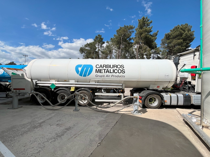
Illustration 3. Tanker truck for road transport of liquefied carbon dioxide.
Thermal consumption
In the case of chemical solvent capture technology, an additional thermal energy input is required, generally through the use of low-pressure steam between 3 – 5 barg. This is important to consider when planning a capture project due to the need for a stable steam supply and for that steam to be of renewable origin.
Since each ton of captured CO2 requires between 1 – 2 tons of low-pressure steam (0.6 – 1.2 MWh/t CO2 of thermal energy), in many cases, even when the project is located in an existing industrial environment, there is not always sufficient residual heat to cover the process’s thermal demand.
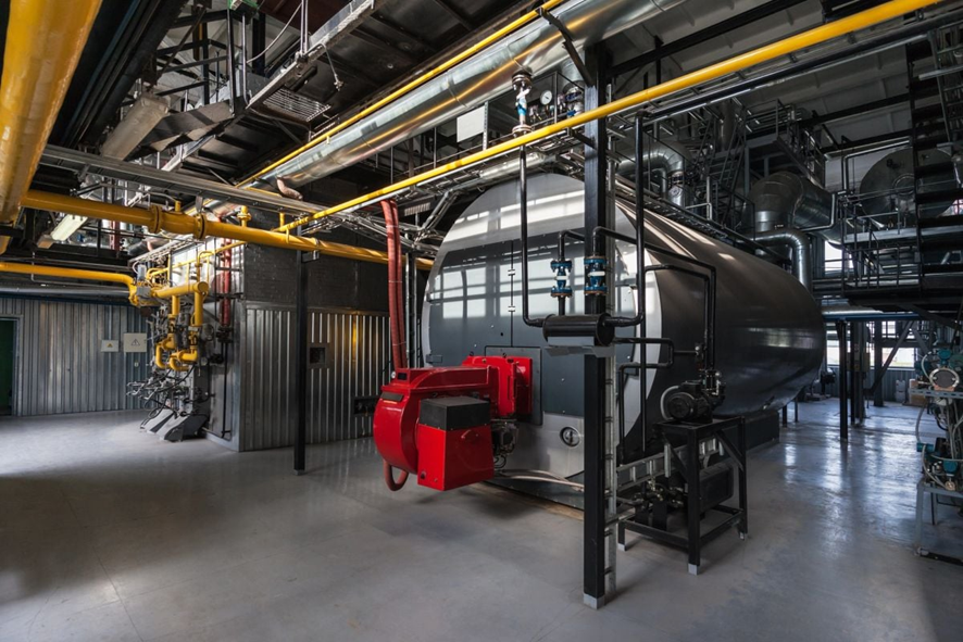
Illustration 4. Industrial steam generation boiler. Source: (CoolPlanet, 2023)
For this reason, potential energy integrations between the capture plant and other processes such as RFNBO production (e.g., renewable methanol or SAF if the capture plant is coupled with a fuel production plant), or the residual heat of the exhaust gases from which CO2 is to be captured, should be considered from the outset, as they allow the need to import heat from other sources to be reduced. This point on energy demands is one of the main aspects to consider in integrating capture and sustainable fuel plants, especially since SAF production is an exothermic process that generates large amounts of steam that can be used as an energy input in the CO2 desorption stage.
As a result of these high thermal demands, auxiliary steam generation systems are commonly required to cover the desorption stage demand. Among the most commonly used solutions are conventional steam generation boilers. However, these boilers should preferably use renewable fuels; otherwise, they would increase the CO2 and derived product carbon intensity. A solution that is gaining strength recently is the use of electric boilers or, failing that, replacing steam circuits with high-temperature thermal fluid systems that allow for direct electrification of the heat supply. These technologies offer the advantage that, when powered by renewable energy, the heat provided to the process does not contribute to GHG emissions.
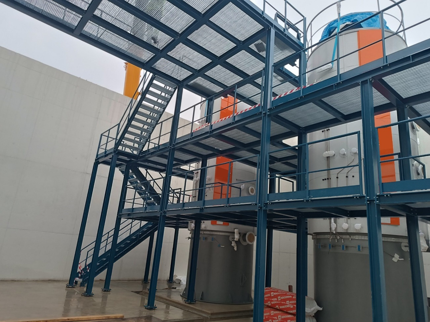
Illustration 5. Electric boilers developed by AITESA. Source: (AITESA, 2024)
General consumption
As a reference, the generic consumption for a capture plant of 100,000 t CO2/year based on amine technology is as follows:
Table 1. Generic consumption of a capture plant with a capacity of 100,000 t CO2/year.
| Parameter | Value | Units |
| Capture capacity | 100.000 | t CO2/year |
| Electrical power | 0,7 | MWe |
| Thermal power | 11,3 | MWt |
| Steam consumption | 18,75 | t/h |
| Cooling demand | 16,4 | MWt |
Integration of capture in RFNBO fuel plants and compatibility with existing processes
When planning a carbon capture project in existing industrial facilities, all factors associated with both the capture plant and the industrial environment in which it will be installed must be considered. For appropriate design ensuring efficient and competitive capture, compatibility of capturing CO2 with the current process must be verified.
Thus, a deep analysis of the carbon dioxide emission source and the current/existing use of the exhaust gas must be conducted, as it is usually either directed to gas treatment systems for contaminant removal before being vented to the atmosphere via a stack or used in energy integration processes within production.
In cases where the exhaust gas is used for energy integration, we find industries that utilize the residual heat from combustion unit emissions for drying processes. In this context, to dry the raw material with the exhaust gas, a phenomenon of dilution with atmospheric air occurs, decreasing the CO2 concentration and thereby complicating the capture process.
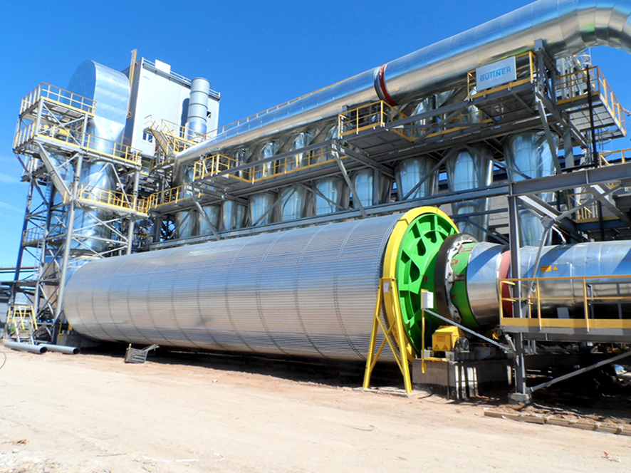
Illustration 6. Rotary industrial dryer. Source: (Buttner, 2024)
In these cases, a valid solution may be installing an air-gas heat exchanger that allows atmospheric air to be heated with the residual heat of the exhaust gas indirectly, thus avoiding CO2 dilution while still drying the raw material. This solution increases the plant’s CAPEX due to the investment associated with the heat recovery system but allows maintaining an adequate carbon dioxide concentration for capture using, for example, amine-based solvents.
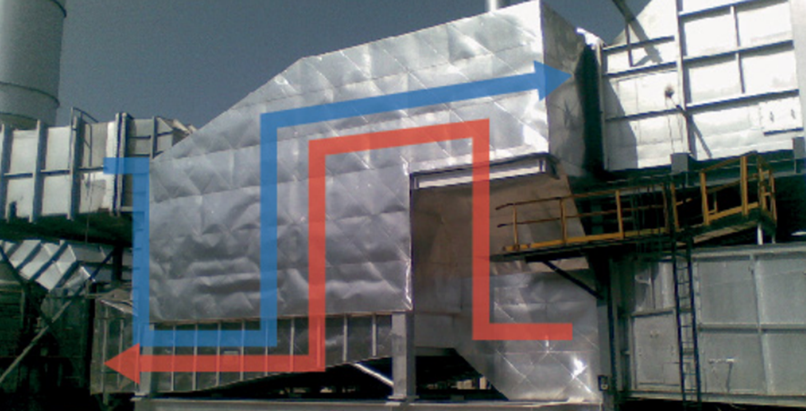
Illustration 7. Heat recovery unit for flue gases from Kelvion Thermal Solutions. Source: (Kelvion Thermal Solutions, 2024)
At the same time, since exhaust gas pretreatment processes require a certain temperature to operate correctly, it is necessary to ensure that the implemented energy integration does not cause the exhaust gas temperature to fall below 200–250 °C before entering the impurity removal section, as these are the optimal operating temperature ranges for sulfur compound removal systems.
For all these reasons, during the design stage of a capture plant, it is not only the capture process itself that matters but also existing processes and even potential co-located CO2-derived fuel production plants, since process integration can lead to significant improvements resulting in cost reductions and more efficient operation.
Don’t forget that at AtlantHy, we work daily on CO2 capture projects with great success throughout our history. Both in consulting and engineering, as well as in subsidy processing.
Feel free to contact us to launch your carbon capture project!
If you liked this article, stay tuned to keep learning in the third part, where we’ll discuss various lessons learned in planning this type of plant… Follow us at AtlantHy Academy!
References
AITESA. (2024). Calderas eléctricas de alta tensión de electrodos. Obtenido de https://aitesa.es/caldera-electrica-industrial-alto-voltaje/
Buttner. (2024). Rotary drum dryers for biomass products. Obtenido de https://www.buettner-energy-dryer.com/en/industrial-dryer-systems/rotary-drum-dryers/
CoolPlanet. (2023). Maximising Boiler Efficiency: Reducing Costs. Obtenido de https://www.coolplanet.io/blog/articles/boiler-efficiency-and-decarbonisation
Global CCUS Institute. (2021). Technology Readiness and Costs of CCS.
Kelvion Thermal Solutions. (2024). Rekuluvo: Combustion Air Preheater. Obtenido de https://www.kts.kelvion.com/_files/ugd/3c9275_1d724936c7794f5ca51ed8a7fdf1ec82.pdf
Perspective. Frontiers in Energy Research.